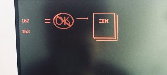
The IBM P75 (and its younger brother, the IBM P70) can be a little tricky to restore and get back up and running, perhaps even more so than your average 30+ year-old computer. Typical issues include bad capacitors, a dead CMOS battery, and having a garbled display. Some other issues may show when you manage to get POST, and the P75 will typically generate error codes 162 and 163 alongside a very disconcerting “NOT OK” image and a graphic to check your IBM manual.
If you are getting these codes (or any other codes) on boot, check this website for a handy list of IBM error codes, along with their meanings. Most common error codes include PS/2 error codes 162, 163, 201, 221, 165, 14901 – all but the 14901 error code should resolve themselves if you replace the CMOS battery and run the IBM reference diskette. The 14901 error code is a bit more tricky – resolving it usually requires disassembling the IBM P70 / P75 and cleaning the contacts on the graphics card as well as the display power and data cables. Sometimes, a recap of the graphics card may be also needed.
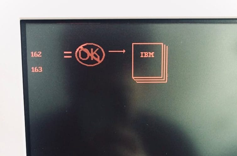
If you cannot get POST, I suggest you consider doing these two things first before moving further:
- Recap the system planar board, the graphics board, and your floppy disk drive – they use various SMD capacitors, most of which will have failed (see link for list and location of capacitors). Failed capacitors can lead to a boot with nothing displayed or a boot and short beeps. You should be able to boot to the screen above once you have recapped the system board and display card.
- Replace the 6V CMOS battery – this is needed to save and preserve your system configuration when the computer is off, so you don’t have to redo your setup each time.
Once you have managed to get the computer to POST (as in, you get a RAM count), you need to get your hands on or make a reference diskette.
Create a Reference Diskette by downloading it here for the P70 and here for the P75. Booting from this diskette is the only way you can configure an IBM P75 – there is no BIOS that is normally found on more modern computers.
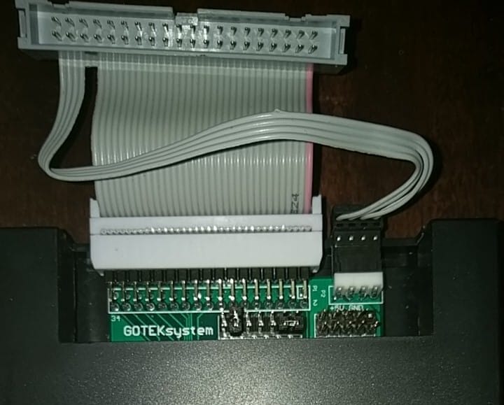
As mentioned, you will likely need to recap the floppy disk drive to boot the reference diskette. If you need to replace the floppy disk drive, you must replace it with an IBM drive as they have a proprietary pinout that is different from standard floppy drives. Alternatively, you can also create an adapter to use a standard floppy disk drive or GOTEK floppy emulator. It is also possible to use an adaptor to get a standard floppy drive to work in the P70 / P75.
If you are having trouble getting the IBM P75 to POST after recapping or replacing the battery, try leaving the CMOS battery unplugged for an hour. Sometimes, a corrupt configuration can be stored in the CMOS, preventing the computer from booting until the contents are reset. After an hour of leaving the CMOS unplugged, try booting the P70 / P75 with no battery plugged in, then run the configuration from the Reference Diskette. Once the configuration is saved, then (carefully!) reattach the battery plug onto its header pins.
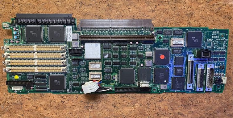
Other issues to consider would be to check the RAM on the motherboard. The IBM P75 supports up to 16 megabytes of RAM through 4 SIMM slots on the motherboard, each of which can accept a 2 MB or 4 MB 70 nanosecond SIMM.
Check if they have been installed correctly or if they require cleaning. I always use isopropyl alcohol and a q-tip to clean connectors on RAM SIMMs or pretty much anything with an edge connector. Also, note that IBM PS/2’s require that the correct “presence detect” pins have been used – these are little solder connections between pads on SIMMs that indicate what kind of SIMM it is to an IBM computer. Basically, the SIMM must be manufactured by IBM for the P70 / P75 to accept them – non-IBM SIMMs, specifically, those that do not utilize the “presence detect” feature, cannot be used unless you modify them.

Take a Closer Look at the IBM P75:
- The Most Powerful Portable – IBM P75
- Take a Look Around (The Outside)
- But wait, there’s more – Under the Hood (Interior)
- Tips & Tricks (Restoration: CMOS Battery, Getting POST)
- Booting Up & Configuring the IBM P75
